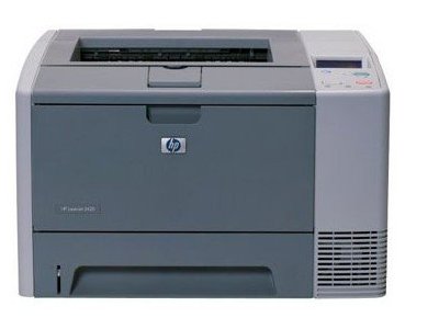
How to install the fuser and rollers in the HP LaserJet 2410, 2420 and 2430 printers. This covers the following parts: Maintenance kit H3980-60001, Fuser RM1-1535, transfer roller RM1-1508, tray 1 pickup roller RL1-0568, Tray 1 separation pad RC1-0939, tray 2 roller RL1-0542, tray 2 separation pad RM1-1298.
Author Archives: Tom Braeger
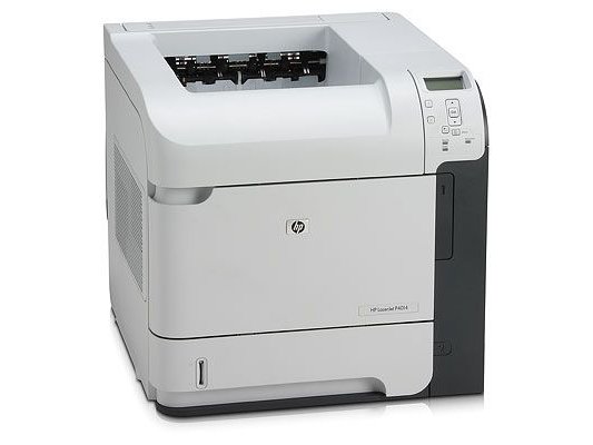
Replacing the fuser and rollers in the HP LJ P4014 P4015 P4515 series printers
How to install the fuser and rollers in the HP LaserJet P4014, P4015, P4515printers. This covers the following parts: Maintenance kit CB388A, Fuser
CB506-67901, transfer roller CB506-67903, tray 1 pickup roller RL1-1641, Tray
1 separation roller RL1-1654, tray 2 pickup roller rm1-0036, tray 2 separation
roller rm1-0037 Multipurpose kit cb506-67905 tray 2 kit cb506-67904
HP 4000 and 4050 maintenance kit installation instructions
HP 4000 and 4050 maintenance kit installation instructions
Covers the installation of the kit part number C4118-69001, fuser RG5-2661 and rollers RG5-4283, RF5-1885 and RG5-3719.
Click here to order the kit
Maintenance kit installation for the HP 4100 Laserjet
Maintenance kit installation for the HP 4100 Laserjet
Covers the installation and replacement of C8057A or C8057-69001, fuser RG5-5063 and rollers R5-3718, RF5-3114 and RG5-5295.
Order the HP 4100 kit here
Genicom 3810 3840 printhead ribbon cable installation
Instructions to Replace 38xx Ribbon Cable(s)
Turn off printer and remove power cord.
Remove top access cover.
Remove main top cover.
-Loosen, but do not remove the 2 screws that hold the rear cover straps. Remove straps and rear cover.
-There are four tabs to release- 2 under the front and 2 on inner part of top cover near where screws were loosened. Push in on these while lifting slowly upward. When all 4 are released, slowly lift the top cover. The top cover had a cable attached to the control panel. If possible, position something like a small box in front of the printer so the top cover caqn set with the cable still attached.
Remove the Printhead. Below is the connector attached to the two ribbon cables. Loosen the screw on the left and remove it with the plastic wedge clanp and save. There should also be some sort of a stretchable boot or clamp you need to remove to the right on this.
At the left, the two ribbon cables attach to one of the circuit boards. Examine the cables, and mark them or make a drawing to show which plugs in on top/bottom and left and right. It is important that these are re-installed correctly on the new cable. . Once released, gently remove the old cables. Reverse the process to install new cables
When re-installing the main top cover, gently move it into place and gently push down. Make sure the washers on the screws you loosened are on the outside, near the head of the screw.
Diagnosing Texas Instruments and Genicom 8920, 8930 & ADP400 Problems
Diagnosing 8920 & 8930 problems:
| Problem/customer complaint | Possible corrective action |
| 1. Doesn’t see paper loaded/installed. 2. Printhead slams and grinds. (No home position) 3. Gets margin errors. |
1st: Clean and/or replace optical sensor. 2nd: Replace upper/right printhead cable. |
| 4. Paper jamming under printhead. | 1st: Check printhead shield for bends or rough edges. (Replace if necessary.) 2nd: Check for proper mounting of optical sensor. 3rd: Clean and/or replace optical sensor. 4th: Clean/replace lower rollers (8930 only). |
| 5. No carriage (printhead) movement. 6. No pins firing on printhead. (No dots on paper/all pins dead) |
Replace driver board. |
| 7. No paper advance. | 1st: Replace driver board. 2nd: 8930 only: check setup for tractor feed enabled. |
| 8. Printer shuts down (powers off) after 3-4 seconds. | 1st: Remove power supply from printer and power up separately. Observe the green LED: ON – Replace driver board. OFF – Replace power supply |
| 9. Won’t communicate with host or prints garbage. | 1st: Check all setup parameters and interface cables. 2nd: Replace logic board. |
| 10. Some pins not firing. | 1st: Replace printhead. 2nd: Replace upper and/or lower printhead cable 3rd: Replace driver board. |
| 11. Touch pad inoperable. No display or partial display. |
1st: Replace control panel. |
| 12. No ribbon advance. | 1st: Replace ribbon tray assembly. |
Complete list of 8920, 8930 & ADP400 spare parts
HP Laserjet 4200 Maintenance Kit Installation Instructions
Click the link below to view the document.
HP 4200 Maintenance Kit Installation Instructions
This describes the installation of the kit Q2429A, fuser Rm1-0013, rollers Rm1-0699, RM1-0037, RL1-0019.
Order the HP LJ 4200 kit here
Maintenance Kit installation instructions for the HP 8100 and 8150 Laserjet printers
Click the link below to view the document.
Hp Laserjet 8100 8150 Maintenance Kit Instructions
This describes the installation of the kit, C3914A or C3914-69001, fuser RG5-6523, Transfer roller RF9-1393 and rollers RF5-1834.
Order the 8100 or 8150 maintenance kit here
HP Laserjet 5000 mainenance kit installation instructions.
HP Laserjet 5000 mainenance kit installation instructions. Click on the link to view the instructions. This covers kit part number C4110-67923, fuser RG5-5455, rollers RB2-1820, RB2-1821, RB1-8865, RF5-3439, RG9-1485, RF5-2634, RG5-3579.
HP LJ 5000 Maintenance Kit Installation Instruction
YouTube – Lexmark T620 T622 Fuser Maintenance Kit Replacement How to Install
YouTube – Lexmark T620 T622 Fuser Maintenance Kit Replacement How to Install.
Click the link above to view the video.
Installation instructions for replacement of the fuser and maintenance kit parts.
Order all your Lexmark printers, parts and supplies online at:
http://www.fastprinters.com
Kit part number 99A2408 or 99A2411 includes Fuser 99A2402 or 99A2405 pickup tire 99A0070 or 40X0070 transfer roller 99A1015 and charge roller 99A1015 printer repair parts
80 Scheduled Maintenance Message


